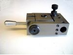
Sometime in the early eighties, I built a tool holder to a design published in Model Engineer, intended to assist in tool retraction during screw cutting and boring operations, photo 1. The article was by ‘Martin Cleeve’, although I cannot verify this. It is odd, as he filed the patent for his retracting swing tool holder in 1970 and this would seem to be the Mk.I version. Perhaps he described both, and I went for the easier option when I made mine.
The component parts, photo 2 consisted of a block that had a reamed 3/8in. dia. hole and was slit along the top to allow adjustment with two Allen screws. A 3/8in. dia. spindle, slightly longer than the width of the block was fitted into this hole. It was threaded at either end to allow the attachment of two arms joined at the ends with a distance piece.
Enjoy more Model Engineer reading in the monthly magazine.
Click here to subscribe & save.
One of the arms had a shallow 7/16in. bore to accept a silver steel disc 3mm thick, which could be pushed with a grub screw to take the cutting thrust and eliminate side play.
The distance piece was drilled for two dowels and two screws to attach the tool holder block. When the tool reached the run-out groove, when in use for screw cutting, the holder could be swung upwards to move the tool clear to allow the return of the tool without disturbing the in-feed setting, photos 3 & 4.
I have not used this facility, as at the time I used a cross slide indexed stop as described by ‘Tubal Cain’ in his book ‘Simple Workshop Devices’. Where I found this tool post really came into its own was when using the holder to accommodate a boring tool, photo 5.
This allowed the boring bar to be swung clear of the workpiece after the tool was withdrawn to allow easy access to gauge the hole without moving the cross slide or moving the saddle right back out of the way.
As I used this tool holder exclusively for all boring jobs, I changed the square tool block to one with a 1/2in. bore to accept boring bars of this size, or smaller diameter ones with suitable split sleeves, or larger bars with the ends turned down to 1/2in. photos 6 & 7.
Recycling
The tool has to be set at a slight angle to the direction of travel to prevent any interference from the side of the cutter as it enters deeper into the bore. That said boring could commence from a hole barely larger than the cutter used. The tools are very stiff as there is no reduction to the diameter as with a normal boring tool. They are ideal for recessing work, as they cut either forwards or sideways. The long curled swarf exits from the front of the workpiece, rather than disappearing down the mandrel bore.
I have since made the retracting version of this tool post using the currently available Hemingway kit, photos 9 & 10. Being primarily designed for Myford lathes, the one-piece tool block and side arms were made from a quite substantial piece of material, allowing it to swing over the long tool post stud. Boring tools are mounted in a slot across the front and screwcutting tools are mounted in a slot in the left arm.
My lathe has no such stud and as I use round tool bits for screw cutting, I made the arms and tool block as built up items similar to the original one made for boring bars, Fig.1. The means of holding the threading tool is really a very short and fat boring bar, photo 11. The left over piece of material from the kit was just the right size to make the body for a QCTP project.
The basic construction of the latter tool is similar to the original, with the tapped holes at the ends of the spindle offset, which locate bronze bushes in the side arms. The spindle is rotated through 90deg. with a handle running in a slot through the centre of the top and rear of the block, moving the tool back and forth via the eccentrically mounted bushes in the arms.
Screwcutting
For screw cutting, the holder is set forward with the handle vertical and the first cut taken. At the end of the cut, the handle is pulled back about 45deg. to withdraw the tool for repositioning it at the start of the next cut.
For boring, the holder is set backwards with the handle horizontal and the cut taken. Again, the handle is lifted to about 45deg. to move the tool clear, allowing it to be withdrawn leaving the cross slide setting. Again the swing facility allows easy gauging of the boring progress. Finish sizing cuts are easier to apply, as there is no resetting of the tool to its previous position before adding another small amount of in-feed.


