A Miniature Pin Type Precision Vice

by

Background

Soba vice in use

To improve work holding on my milling machine, I have purchased a Soba precision vice from the Chronos catalogue. The vice is ground all over, allowing clamping on its sides or end. When the jaw is tightened, it is pulled forward and downward, reducing any tendency to lift, photo 1.

 
The catalogue also showed miniature versions of this type of vice and I thought such an item would be very useful. Using a piece of 1 1/2in. x 1/2in. mild steel flat bar and a piece of 3/4in. square bar, a base could be built up, and a piece of 1in. square bar would serve for the moving jaw.
 
The finished miniature vice
The vice showing capacity
 The component parts


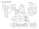
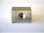
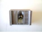
What follows is my attempt to make a 1 1/2in. version of the vice with a 65mm capacity. Photos 2 and 3 show the finished vice and photo 4 shows the component parts. See also drawing GA Pin Type Precision Vice.


Article continues below…
Advert

Enjoy more Model Engineer reading in the monthly magazine.
Click here to subscribe & save.
The Body Fig. 1
 
The base and fixed jaw

A piece of the flat bar was squared up on the ends to a length of 110mm and one side dressed with a file for the pin hole positions to be marked down the centre of this side. These holes were then carefully drilled through 5mm diameter and countersunk to a depth of 1mm on both sides, photo 5.


A centre line was marked on one of the wide faces and the centres of the ends of the slot marked and punched. Two 6mm diameter holes were drilled at these marks and the piece mounted in the milling vice on parallels to give a clear passage for cutting the slot.


With a 6mm slot drill mounted in the chuck, and the cutter aligned with the left hand hole, cutting commenced with 2mm down feeds, travelling left to right to the stops for each cut until through at the bottom. The cutter was then replaced with a 3/8in. (9.5mm) slot drill and the process repeated.
 
The base and fixed jaw

With the table locked, a 10mm end mill was slowly fed down to full depth and the table released to carefully traverse along the slot until it just made contact with the end where it was withdrawn and the table moved the last bit to contact the stop and locked. The cutter was again fed down to depth and the table released to take a final cut to the beginning. This yielded a straight slot with a good finish to the sides and ends, photo 6.


A countersink bit is fed down to a cut of 0.5mm and traversed to the end of the slot, providing a neat chamfer around the slot. This chamfering was repeated on the other side of the slot.Clamp the base to the mill table, pushing against a snug fitting parallel in the rear T slot. Also use a piece of flat stock secured to the table at the front to keep it in place. With a 10mm end mill, take the first pass along the front, 2mm deep with 3mm in-feed.


Add 0.5mm to both feeds and repeat. Measure the step to determine the exact amounts for the final pass. Reverse the piece and repeat this procedure for the other step.Making sure you are at the right end, mark and punch the positions of the holes for the fixed jaw securing screws and dowel pins. Drill the screw holes M5 tapping size and the pin holes 3mm, photo 6.
 
The base and fixed jaw

I also provided slots for clamping on the ends by plunging a 16mm x 4mm woodruff cutter 5.5mm deep on the centre line. You could also mill from the top to provide clamping clearance instead of using a woodruff cutter, photo 7.


Fixed Jaw Fig. 2
 
Cut a piece of 3/4in. square bar 40mm long and draw file all sides to a good finish, ensuring all faces are square to each other. Either face or mill the ends to clean up and bring the piece to length.
 

Use a square to align the jaw piece flush with the end of the base and clamp it in place to leave the screw pilot holes clear, again check with a square after tightening the clamp. Drill through the first hole to a depth of 14mm, checking nothing has moved before drilling the second hole. Remove the clamp and tap the holes in the jaw.

Article continues below…
Advert
 
Open up the holes in the base to 5mm and counterbore 8.5mm, flat bottoming the holes to a depth of 5.2mm, or whatever is needed to bring the heads of the screws just below the surface.
 
Assemble the pieces using the square to keep the ends flush and when all is well, firmly tighten the screws. Drill the dowel holes to depth in the jaw and press in the dowel pins. Draw-file the bottom to remove any burrs from the counterbores and to bring the dowels flush.
 
Moving Jaw Fig. 3 and photo 8
 
The moving jaw

Cut off a piece of 1in. square bar 40mm long and clean up the sides and face or mill the ends to length. Although one side is over width, leave it for now as a backup for cutting the slot at the bottom. Scribe a centre line for the slot and mount the piece by its ends in the milling vice.


Set the line central and lock the Y feed, zeroing the dial after taking up any backlash. With a 10mm end mill, take a 2mm deep pass down the centreline, followed by a 1mm pass. Check that the slot is actually 10mm wide and in the direction you took up the backlash. Put on a feed of 9.5mm and relock the Y feed. The feed needs to be into the cut, so move the table to the appropriate end and again take cuts of 2mm followed by 1mm depth. Measure one of the steps in the base and compare this with the remaining land on the jaw. Apply the required Y feed and take another pass.


Take up backlash in the opposite direction and zero the dial on the Y feed. Move the feed 19.5mm in this direction and take the two passes. This time, measure between the steps in the base and compare with the width of the slot. Apply this amount of Y feed, minus 0.1mm and take a cut in the appropriate direction of about 10mm and try the base, which needs to be a firm sliding fit. Take further light cuts until this is achieved, then complete the final pass. Clean up all edges and try the fit on the base. If still on the tight side, rub each side of the jaw slot along a fine flat file with a safe edge to get a smooth sliding action.

Article continues below…
Advert
 
Mark out the amount to be removed from the top to bring it level with the fixed jaw and remove the excess material. Mark the lines at 9mm and 13mm as Fig. 3 for the edges of the bevel and carry these marks around the ends. Saw off the excess just clear of the lines. Holding by its ends, set the jaw in the mill vice on a small vee block to finish the bevel with a fly-cutter.
 
Mark the position of the 5mm diameter hole and drill this just short of breaking through. With a 1/2in. countersink bit, countersink to the full width of the cutter. If a ball ended cutter is available of this size, a better job can be made by feeding this down 6mm. Remove the V block and use the 5mm drill to align the piece in the vice again to finish the hole.
 
The toggle pocket

Set the jaw in the vice resting on the bevel (A) and use the drill to align the 5mm hole centrally. Open the hole in stages to 10mm x 15mm deep at the full diameter. Replace the drill with a 10mm end mill and take 2mm cuts until the toggle pocket is 15mm deep, photo 9.


Toggle Fig. 4 and photo 10
 
The toggle

Set a piece of 10mm square bar in the 4 jaw chuck with about 20mm protruding and face the end. Drill and tap M4 to a depth of 12mm and deeply countersink. Turn down to 7.5mm Dia for a length of 12mm, and then part off leaving a 8mm length of square material. Drill the 4.7mm (3/16in.) cross-hole as per Fig. 4 and leave for now.


Washer Fig. 5 and photo 11
 
The spherical washer

Holding a piece of 1/2in. diameter material in the three-jaw chuck, turn down a 4mm length to 11.5mm diameter if using the countersunk hole, then form a 7mm radius on the end. Drill 4mm diameter x 5mm deep. Polish the radiused end and part off to leave 0.5mm of parallel material after the radius as per the sketch.


Pin Fig. 6 and photo 12
 
The clamping pin

This is just a 37mm length of 3/16in. diameter rod chamfered on both ends. On both of these vices, I found that turning the respective jaw tightening Allen screws with the fingers to initially set the jaws was unsatisfactory, as was using an Allen key.

Article continues below…
Advert


My answer was to make a knurled knob bored to a close fit on the screw head, with a piece of hexagon key pressed into the bottom of the hole to fully engage in the socket with the knob fully covering the head. In fact the larger knob has three radial holes to accept a tightening pin for the final tightening of the vice and this is used exclusively.
 
Knob Fig. 7 and photo 13
 
The tightening knob

Knurl 12mm on the end of a piece of 19mm diameter bar and reduce 4mm long to 13mm diameter. With a 90deg. V tool, chamfer the end and the edge of the knurling on both sides. Traverse the tool to the left of the knurling by the width of the parting blade to give it a good start.


Drill the end 6.7mm diameter to a depth to fully engage the head of the screw, and drill into the bottom of this hole 3.5mm for 2mm and at 3mm for a further 4mm deep. Use a 5mm drill to provide a small lead in chamfer.
 
Cut 7mm off the leg of a good quality Allen key by scoring all round and snapping it off. By far the best way to score the key and also HSS tool bits is to use a cut off disc in a mini drill, thereby preserving the pristine corner of your bench grinder’s wheel. Form small chamfers on one end of the piece of hexagon key and grind the other end square, leaving sharp corners.
 
Grip the chamfered end in the jaw tips of the tailstock chuck and bring it up to the knob. Use the tailstock feed to start the key into the hole, making sure it is in quite tight then release the tailstock and move it out of the way for parting off the knob.
 
Press the key in flush using the bench vice and insert the shortest M4 Allen screw you can find, using this as the means to complete the pressing so there is full engagement with the key when the head is fully covered.
 
Assemble the screw, washer and toggle to the moving jaw and bring the jaws together. Insert the pin in the first hole and check that the jaw will tighten fully. Slacken the jaw and check that it will open at least 12 mm. Some final tweaking of the screw seat and hole may be required. With the jaw fully forward and back, observe underneath to see what has to be removed from the toggle to keep it below the base of the vice. The final shape is as Fig. 4.
 
Finishing Off
 
The finished vice in use

Assemble the vice and lock the jaws tightly, use a fly-cutter able to sweep the full width of the jaws to bring the tops level. Draw file all surfaces to a smooth finish and take a little extra material off the sides of the moving jaw. This allows the jaw to be released whilst still gripped in a larger vice, if it is to be used in this way. Chamfer all exposed edges and the vice is ready to go, photo 14.


Further Thoughts
 
An alternative method of engaging the toggle is to fix a short pin to locate in ‘half holes’ in the base, which would need to be at least 16mm thick. After the 10mm slot is milled in the base, a further cut is taken at the bottom with a 16mm end mill to just break the centres of the pinholes. With a suitable length of pin fixed into the toggle, it only needs slackening to slide the jaw to a new position and re-engage the pin in another curved slot. Sk. 1 shows the idea for the more adventurous with a better stock of materials than I have.
 
Another advantage of this method is that it allows a 5mm slot to be milled down the sides along the line of the holes to provide for clamping down. As it is, I only had material this size so if clamping is required, it only needs to have a couple of clamps made with 5mm pins in the ends. This is the method used on my mill.


Advert

Enjoy more Model Engineer & Model Engineers’ Workshop Magazine reading every month. Click here to subscribe.


Article Tags:

About the Author